
Variable impedance liners for aero-engines
Summary
Acoustic liners application within the nacelle walls is a well established passive noise damping technique in modern turbofan engine. Improved acoustic liners should be developed to improve the maximum noise attenuation induced by acoustic liners and broaden the attenuation frequency range by using non-uniform acoustic liners.
The high bypass ratio of modern turbofan engine results in that the
tonal noise decrease while the broadband noise is becoming a more and
more important contributor in engine noise. Thus improved acoustic
liners should be develop to: 1. Improve the maximum noise attenuation induced by acoustic liners. 2. Broaden the attenuation frequency range by using non-uniform acoustic liners.
Engine intake noise radiation:
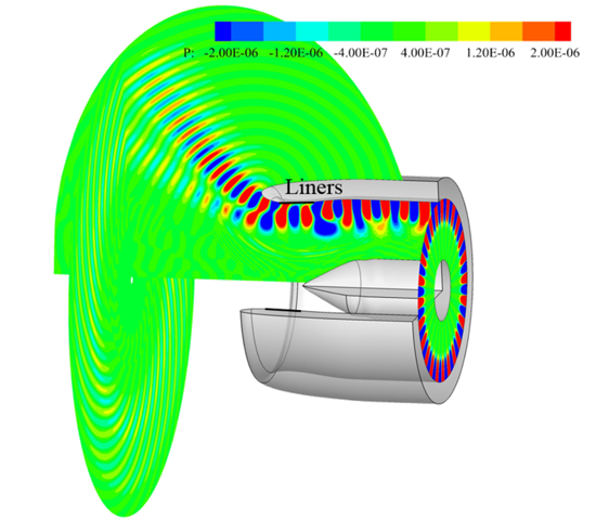
In the m24n1 case study with no acoustic liner treatment, the bulk of the
acoustic energy is concentrated towards the upper wall. As the wave
propagates across the inlet there is no change in the acoustic
wavelength. However, the wave is diffracted by duct lip.
Non-uniform liner distribution:
The possibility of reducing radiated noise by varying the liner properties
along the duct in both axial and circumferential directions was investigated. A
serrated joint liner distribution was proposed
Reference
Mr. Jingwen Guo is supported by a PhD fellowship from
HKUST. Part of the study was supported by the Hong Kong
Innovation and Technology Commission (Ref. ITS/038/FP15).